For several years I have mostly used my Yaesu FT-847 with the annoying rear fan disconnected, but lately I have noticed that the radio gets quite warm to the touch, and noted some frequency drift when running high-dutycycle modes like WSJT for extended (hours!) periods of time. I cannot accept the obvious solution - letting the fan run, when not really needed most of the time! The solution: Thermostatic control.
The solution developed can be applied to any low-voltage DC-driven fan, but here it's been implemented specifically for the FT-847.
None of the component values are critical, and any N-channel MOSFET with a reasonably low on-resistance can be used. I selected the IRF510 because I had a supply already in my component drawer, and because it's cheap (~ 0.3$)

The circuit has been mounted on a hand milled PCB (size 10x20mm). In the picture the NTC resistor has just been soldered on with long leads for testing purposes. Where available SMD components have been used.
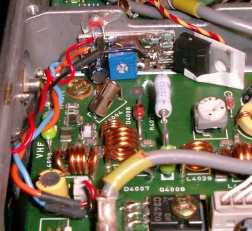
Here the Fan controller has been mounted in the VHF/UHF PA compartment of the FT-847, note that the 144MHz cable to the Rx side has been removed for clarity. The MOSFET has been wrapped with a small piece of electrians tape to make sure that there is no contact between the Drain flange and the PA board. The controller PCB itself has been fastened to the chassis with a small piece of adhesive foam. The lead from the fan to the connector has been cut, the red lead to the fan soldered to the + 12V pad and the black the the Drain pad on the controller. The rest of the leads, leaving the connector has been taken to the + and - 12V pads on the controller using two approx. 5 cm long leads. The NTC resistor has been glued to the chassis for positive thermal contact.
Final adjusment for approx. 3.2V on the Gate finishes the job.
Now a temperature increase of 5-6 degrees centigrade will cause the fan to start, and it'll continue to run at required speed until everything has cooled down sufficiently. Note that the supply voltage for the fan drops about 1.5V when transmitting, causing the fan to increase speed in Rx mode (until subsiding with temperature decrease).
(Source: http://www.ham.dmz.ro)